MechAction, Inc.

Expertise in Nanomechanical Testing
MicroIndentation Testing


Introduction
Microindentation, which shouldn't be confused with conventional microhardness testing, is instrumented indentation technique at force and depth scales larger than the nano-range. Microindentation can be used to determine not only hardness, but also other mechanical properties (Young's modulus, Yield Stress, etc.) just like the nanoindentation technique.
Instrumented indentation technique (including both nano- and micro-indentation) is achieved using a high-resolution system that can drive an indenter tip made of diamond into and withdraw it from a sample material. During the process, the loads and displacements of the tip are recorded by positional sensors, from which mechanical properties can be derived. In the past few decades, this technique has been developed sufficiently to satisfy the increasing needs of nano and micro-scale materials and devices characterizations.
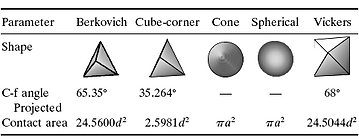
While nanoindentation usually sticks with Berkovich Tip, Microindentation tends to use both Berkovich and Vickers indenters. Berkovich is a sharper tip than Vickers, but it is also more fragile. For high load indentation (usually a few Newtons or greater), the Vickers indenter is a safer option for deep surface penetration. As the area functions of Berkovich and Vickers tips are essentially the same, the test results from both tips are comparable.

Vickers Tip

Berkovich Tip

Nanoindenter System with Microindentation Add-on Feature

Theory
The Oliver&Pharr method for nanoindentation was proposed in 1990s and is still widely adopted to determine various materials hardness and elastic modulus. Though the O&P method has its limitation specially when dealing with substrate effects and soft materials (such as hydrogels and biotissues), it still provides a satisfactory approach to the measurement of true mechanical properties at small scales.
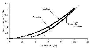
The O&P approach is to fit the unloading curve of the load-displacement data with a power-law relation. Where B and m are empirically determined parameters, h is the displacement, P is the load, and hf is the final displacement after complete unloading of the indenter tip. Thus, S the slope of nanoindentation unloading curve can be derived as below:
The equations of reduced Young’s modulus (Er) and hardness calculation (H) are given as:
where A is the projected contact area of contact under load, and β is a constant that depends on the geometry of the indenter tip. The projected area is calculated by evaluating an empirically determined indenter area function A=f(hc) at the contact depth. This area function is also known as the tip shape function, which is related to the geometry of the indenter. For a perfect Berkovich tip, (A) can be represented as 24.56hc^2. It needs to be mentioned that in practical use, the tip geometry will not be perfectly sharp. Thus a calibration of the contact area needs to be introduced using the equation above where Ci are the fitting constants.
Oliver and Pharr were the first to suggest (A) as function of hc instead of hf. The contact depth (hc) is usually smaller than the displacement (h) for a sink-in situation (hc>h, when pile-up). The figure below shows the schematic of a section through an indentation and the relationships between various parameters. In Oliver & Pharr’s method, the contact depth hc is estimated the equation below, where ε is a constant that depends on the indenter geometry. Nowadays, most of the Nanoindenter systems use the Oliver & Pharr method to calculate the materials mechanical properties.
Indenters with various shapes are used for different purposes. Pyramidal indenters also well known as Berkovich tips are probably the most frequently used shape. The three-sided pyramid can ground to a very small point, which will keep its geometry to the minimum scales.


Micro vs Nano Indentation
Microindentation
Nanoindentation
Test Materials
Very hard materials
(hard ceramics and high strength alloys etc.)
Hard, Intermediate, and soft materials (metals, plastics, polymers, etc.)
Load Applied
mN to N
(up to 30N)
µN to mN
(Min. 10 µN)
Sample Thickness
A few µm up to bulk scale
A few nm to a
few µm
Max Indent Depth
50 µm
20 µm
Resolution
Lower
Higher
Noise Floor
Higher
Lower
Measurements
1. Young's Modulus
2. Instrumented Hardness (In Pa (Pascal) unit)
3. Fracture Toughness
4. Creep
5. Relaxation
6. Modulus/Hardness vs Depth
Standards
1. ASTM E2546 Standard Practice for Instrumented Indentation Testing
2. ISO 14577 Instrumented indentation test for hardness and materials parameters