MechAction, Inc.

Expertise in Nanomechanical Testing
NanoIndentation Testing


Introduction
Nanoindentation, also known as instrumented indentation technique (IIT), is achieved using a high-resolution system that can drive an indenter tip made of diamond into and withdraw it from a sample material. During the process, the loads and displacements of the tip are recorded by positional sensors, from which mechanical properties can be derived. In the past few decades, this technique has been developed sufficiently to satisfy the increasing needs of nano-scale materials and devices characterizations.
The earliest indentation technique traces back to the ancient times when people bit on gold coins to check its authenticity. The ancient gold coins were usually made from pure gold metals, which are ductile and relatively soft. A counterfeit gold coin is usually mixed with other metals like copper which will lesson the coin value. However such process will also harden the coin, which leads to a different result when you bite on it: pure gold will have a dent after biting, while counterfeit gold will grant you a broken tooth! This simple phenomenon dictates the truth of indentation: to measure the hardness of materials (resistance to permanent damage from an outer force).
The human body is probably the most sophisticated indentation machine. You have your teeth as the indenter tip, the jaws and muscles to provide force, while the brain gives you the sensation that the material you bite on is whether soft or hard. The modem indentation systems simply mimic such function by replacing the teeth with a diamond indenter, the jaw with a force actuator, and the brain with force/depth sensors.
One of the very first instrumented hardness testers was the Brinell hardness tester. Introduced in 1900s, the Brinell tester employs a spherical indenter and a fixed load to make indentation impressions on the material surface. By optically measuring the imprint size, the contact pressure (hardness) can be calculated. However, the spherical shape of the indenter limited Brinell's applications on hard materials. In 1919, the first Rockwell Hardness Tester was introduced, which has kept its popularity in the industrial fields through modern days. Compared to Brinell's spherical indenters, the Rockwell employs a cone shape indenter (Rockwell also employs spherical indenters depending on its scales), so it can penetrate deep into materials, which makes it a great tool for hard materials hardness measurements. The Rockwell also introduced the pre-load concepts, which takes away certain influence of the elastic deformation on hardness measurements. Rockwell scales from A through G depending on different loads and tips used. Just about 2 years later, an even "sharper" hardness tool was introduced in 1921: The Vickers Tester employs the so-called Vickers Indenter (a 4-face pyramid shaped tip), which is sharper than a Rockwell cone tip. Unlike Rockwell, the Vickers indenter is a one-tip-fit-for-all situation, as the required calculation is independent of the Vickers tip size. The Vickers Systems are still very popular these days and preferred by hard metals/alloys and ceramic industries.
In the last 2~3 decades, as the world has been more and more inspired by the nano-scale materials and devices, instrumented indentation, inexorably, followed this “expanding” trend. Researchers started to realize the limitations of conventional microhardness testers: 1. The system sensitivity and resolution cannot satisfy the needs of small (submicron) scale measurements; 2. Cannot measure other mechanical properties such as Young's Modulus; 3. Vickers/Knoop tip imperfection. After years of development, a new type of tool called Nanoindenter was introduced to the market in early 90s to satisfy the urgent needs of nano-mechanical testing. The biggest differences of Nanoindenter compared to a microhardness tester are: 1. Change from Static loading to Quasi-Static or Dynamic loading 2. The load/depth data is recorded through both loading and unloading process of indent; 3. Usage of Berkovich indenter (a 3-face pyramid shaped tip). With nanoindentation technique, the measurements of not just hardness, but also Young's modulus, yield strength, fracture toughness, and many other mechanical properties at nanometer scale becomes achievable.


Bite on the gold coin
"Soft" feeling
Big dent on the coin
"Hard" feeling
Small dent on the coin
Pure Gold
Counterfeit Gold
Evolution of Instrumented Indentation


(1900-Present)
Brinell Hardness Tester

Spherical Tip
(1919-Present)
Rockwell Hardness Tester
Cone Tip
(1921-Present)
Vickers/Knoop Hardness Tester

Vickers Tip
(1990-Present)
Nanoindenter

Berkovich Tip
Theory
The Oliver&Pharr method for nanoindentation was proposed in 1990s and is still widely adopted to determine various materials hardness and elastic modulus. Though the O&P method has its limitation specially when dealing with substrate effects and soft materials (such as hydrogels and biotissues), it still provides a satisfactory approach to the measurement of true mechanical properties at small scales.
The O&P approach is to fit the unloading curve of the load-displacement data with a power-law relation. Where B and m are empirically determined parameters, h is the displacement, P is the load, and hf is the final displacement after complete unloading of the indenter tip. Thus, S the slope of nanoindentation unloading curve can be derived as below:
The equations of reduced Young’s modulus (Er) and hardness calculation (H) are given as:
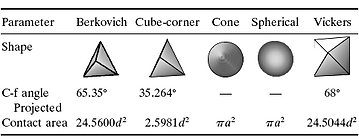
where A is the projected contact area of contact under load, and β is a constant that depends on the geometry of the indenter tip. The projected area is calculated by evaluating an empirically determined indenter area function A=f(hc) at the contact depth. This area function is also known as the tip shape function, which is related to the geometry of the indenter. For a perfect Berkovich tip, (A) can be represented as 24.56hc^2. It needs to be mentioned that in practical use, the tip geometry will not be perfectly sharp. Thus a calibration of the contact area needs to be introduced using the equation above where Ci are the fitting constants.
Oliver and Pharr were the first to suggest (A) as function of hc instead of hf. The contact depth (hc) is usually smaller than the displacement (h) for a sink-in situation (hc>h, when pile-up). The figure below shows the schematic of a section through an indentation and the relationships between various parameters. In Oliver & Pharr’s method, the contact depth hc is estimated in the equation below, where ε is a constant that depends on the indenter geometry. Nowadays, most of the nanoindenter systems use the Oliver & Pharr method to calculate the materials mechanical properties.
Indenters with various shapes are used for different purposes. Pyramidal indenters also well known as Berkovich tips are probably the most frequently used shape. The three-sided pyramid can ground to a very small point, which will keep its geometry to the minimum scales.


Advantages
Nanoindentation has numerous advantages. First, it can be used to evaluate not just the hardness values, but also other properties like Young's Modulus and Yield Stress. Unlike the microhardness tester, nanoindentation does not require a powerful microscope to measure the impression of the indentation. The modulus/hardness and other properties can be obtained automatically right after the test is done. Nanoindentation technique is also ideal for testing nano-scale thin films and materials, as it can limit the indentation depth to reduce substrate effects. The micro and macro test might indent too deep and only measure the composite values. A general rule of thumb for thin film nanoindentation is to indent no more than 1/10 of the film thickness. However, it needs to be mentioned that the surface roughness will have an influence on the nanoindentation data, if the indent depth is too shallow. To overcome roughness, the final depth of indentation should be at least 20 times of the surface roughness. For a very thin yet very rough coating, it is suggested to cut the sample and perform indentation at the cross-section to avoid both substrate effects and surface roughness. There are numerical or empirical solutions like Doerner&Nix, Gao, and Zhou&Prorok models to derive the true film mechanical properties regardless the indentation depth. Furthermore, nanoindentation is ideal for small scale creep, relaxation, visco-elastic, and dynamic mechanical measurements. The stability of a nanoindentation system is outstanding which allows long term holding of the force or depth signals. Last but not least, nanoindentation when combined with heating, cooling, and humidity elements can provide unparalleled environmental studies of certain materials operated at non-ambient conditions.
Measurements
1. Young's Modulus
2. Instrumented Hardness (In Pa (Pascal) unit)
3. Vickers/Knoop/Martens Hardness
4. Stress-Strain Curve
5. Yield Stress
6. Fracture Toughness
7. Creep
8. Relaxation
9. Dynamic Mechanical Properties (Storage/Loss Moduli)
10. Modulus/Hardness vs Depth
Standards
1. ASTM E2546 Standard Practice for Instrumented Indentation Testing
2. ISO 14577 Instrumented indentation test for hardness and materials parameters